WMSIC Electronic Components

MSKSEMI AON7401-MS AON7401

ModelAON7401-MS
PackageDFN3x3-8L
BrandMSKSEMI
Price Price on request Electronic component prices change quickly with market supply and demand. Please refer to the latest WMSIC quotation for current pricing.
Configuration
1 options
Configuration 26+

Available for RFQ

Technical data

Product details

19 specifications

Core information

Product name
MSKSEMI AON7401-MS
Type
MSKSEMI
Minimum package
5000 圆盘

Technical parameters

Electronic Component
MSKSEMI
Electronic Component
AON7401-MS
Electronic Component
1
Package
DFN3x3-8L
Electronic Component
1 P
Type
P
Electronic Component
MOSFET
Electronic Component
0.054g
Electronic Component
1
Electronic Component
BM0230826848
Operating Temperature
55℃~+150℃
Power Dissipation(Pd)
37W
Electronic Component
5000
Voltage(Vdss)
30V

For datasheets, package documents, compatible-part guidance, or other technical resources, contact WMSIC customer service. Availability is confirmed case by case.

AON7401-MS 产品概述

一、概述

AON7401-MS 是美森科(MSKSEMI)推出的一款 P 沟道功率 MOSFET,面向需要高电流、小尺寸和快速开关的电源管理与功率切换场景。器件额定漏源电压为 30V,低导通电阻与较小的栅极电荷量使其在高侧开关、小体积负载切换及便携设备电源管理中具有良好应用前景。封装为 SOD-123,适合对空间和封装高度有严格限制的应用,但在布局与散热设计上需额外注意。

二、主要参数

  • 类型:P 沟道 MOSFET
  • 数量:1 个 P 沟道
  • 漏源电压 (Vdss):30 V
  • 连续漏极电流 (Id):50 A(器件额定,实际受封装与散热限制)
  • 导通电阻 RDS(on):13 mΩ @ Vgs = -10 V, Id = 30 A(典型测量条件)
  • 最大耗散功率 (Pd):37 W(在规定散热条件下)
  • 栅极电荷量 Qg:22 nC @ 4.5 V(用于估算栅极驱动能量)
  • 输入电容 Ciss:2.215 nF
  • 输出电容 Coss:310 pF
  • 反向传输电容 Crss:237 pF
  • 工作温度范围:-55 ℃ 到 +150 ℃
  • 品牌:MSKSEMI(美森科)
  • 封装:SOD-123

三、电气与热特性说明

  • P 沟道 MOSFET 需要负向栅压(Vgs 为负)才能打开,典型完全导通驱动电压为 -10 V(RDS(on) 标注条件)。驱动时须保证栅极电压相对于源极为负值以达到标称 RDS(on)。
  • RDS(on) 在给定驱动条件下非常低(13 mΩ),在中高电流下可保证较小的导通损耗,但导通损耗与电流平方成正比。例如在 30 A 时,理论导通损耗约为 P = I^2·R ≈ 30^2·0.013 ≈ 11.7 W;在 50 A 时接近 32.5 W,接近器件 Pd 标称值。因此在高电流工况下必须保证足够散热。
  • 栅极电荷 Qg = 22 nC(于 4.5 V 测得)意味着栅极驱动能量较小,可实现较低栅极驱动损耗。栅极能量近似为 E ≈ 0.5·Qg·Vdrive(若用 4.5 V 驱动,则 E ≈ 0.5·22nC·4.5V ≈ 49.5 nJ;在 100 kHz 开关频率下,栅极驱动功耗约 4.95 mW)。实际驱动电压与频率增加时,驱动损耗线性上升。
  • 器件电容(Ciss、Coss、Crss)对开关瞬态、回灌和 EMI 有直接影响:较大的 Ciss 会增加栅极能量需求,较大的 Crss(米勒电容)会影响开关过渡过程,需要配合合理的门极回路与阻尼设计。

四、典型应用场景

  • 电池供电设备的高侧开关与电源反向保护(便于在输入端实现简单的电源断开/保护)
  • 便携式设备、移动电源的负载切换与电源路径管理
  • 同步整流、电源管理 IC 中的 P 沟道高侧开关(低压、中电流场合)
  • 音频静音/电源管理、USB/Type-C 电源保护等需要小体积功率开关的场合

五、设计与布局建议

  • 散热:SOD-123 封装受限,实际可流经的高电流受 PCB 铜箔面积与散热路径限制。建议在 PCB 上使用大面积铜箔、加热沉或多层过孔导热,以降低结-壳热阻并充分利用器件 Pd。高电流长期工作前应做温升测试。
  • 布局:保持漏极/源极主电流回路尽量短、宽,减少寄生电阻与感抗;门极驱动回路应短且有适当的串联门极电阻(例如 4.7–100 Ω,根据 dv/dt 与环路情况调节),以抑制振荡并控制开关速率。
  • 保护:在有电感负载或输入瞬态的场合加入 TVS、RC 阻尼或缓冲电路,防止过压和尖峰使 Vds 超限。对栅极建议并联下拉/上拉电阻(根据 P 沟道逻辑可置为上拉),避免悬浮导致误导通。
  • 驱动:确保驱动器能提供足够电压幅度(负向 Vgs),并注意门极电压不要超过器件额定 Vgs 限值(通常 ±20 V,但以厂方数据表为准)。

六、使用注意事项

  • 器件参数(如 Id、Pd)受封装和 PCB 散热设计影响,数据表的额定值通常在特定测试条件下测得,实际工程使用需验证热性能。
  • P 沟道器件的导通控制为负向栅压,接口逻辑与 N 沟道不同,设计时注意信号极性与电平转换。
  • ESD 与钳位保护:功率 MOSFET 对静电敏感,装配与测试注意防静电措施。

总结:AON7401-MS 在 30V 等级下提供了低 RDS(on)、较小栅极电荷与较高额定电流的组合,适合空间受限且要求高效切换的小功率/中功率电源管理场景。设计时需重视封装散热限制与驱动电压极性,合理的 PCB 布局与保护电路能显著提升稳定性与可靠性。若需更精确的热阻、开关能耗曲线或典型应用电路,建议参考厂方完整数据手册或联系厂商技术支持获取进一步参数。

Request for quote

Send RFQ

Use the form for single models, category sourcing, and multi-line BOM requirements.

Send your target model and quantity.

Product sourcing intelligence

Model, package, availability, and BOM fit reviewed before quotation.

WMSIC turns product data, package visuals, BOM context, and sourcing signals into practical RFQ notes for buyers.

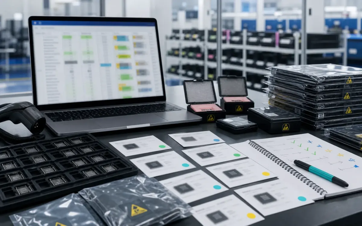
Electronic component model and package intelligence review on an ESD-safe inspection bench

Model & package intelligence

Model text, package form, tray or reel details, and visual evidence are reviewed together before RFQ feedback.

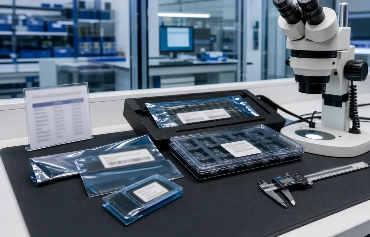
BOM matching and alternative component comparison workstation with protected IC samples

BOM matching & alternatives

BOM lines are compared by package, parameters, quantity, and workable alternatives for cleaner sourcing decisions.

Electronic component sourcing availability dashboard with ESD-protected samples

Sourcing availability signal

Stock routes, quotation confidence, lead-time notes, and shipment feasibility are checked before sales follow-up.

Buyer sourcing scenarios

Examples of how common component sourcing requests are organized.

Typical RFQ scenarios based on the WMSIC form fields, catalog data, manual review steps, and shipment preparation workflow.

The buyer shares the full part number, package requirement, quantity, destination, and available product photos so the quotation can record the exact version under review.

Package confirmation Typical RFQ workflow

A multi-line BOM is organized into direct sourcing lines, lines that need package clarification, and lines where alternative-part review is permitted.

Mixed BOM triage Typical RFQ workflow

The original manufacturer part number, datasheet revision, application, critical limits, and acceptable changes are collected before possible candidates are discussed.

Obsolete-part review Typical RFQ workflow

Sample quantity, minimum packing, package format, target date, and courier destination are kept together in one RFQ conversation.

Small-batch request Typical RFQ workflow

Package photos, model markings, board context, and the quantity needed for repair help focus the sourcing review on the relevant version.

Repair batch evidence Typical RFQ workflow

When a suffix or package note is incomplete, the response records the open difference and requests buyer confirmation before procurement proceeds.

Model suffix clarification Typical RFQ workflow

Packing format, carton notes, invoice details, courier option, destination, and tracking handoff are coordinated around the confirmed order.

Export handoff Typical RFQ workflow

The request connects the previously used model, current demand, package evidence, target timing, and replenishment sourcing route.

Replenishment inquiry Typical RFQ workflow

Related products

Packaged components ready for RFQ.