Model & package intelligence
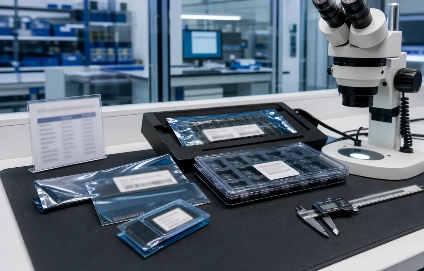
Model text, package form, tray or reel details, and visual evidence are reviewed together before RFQ feedback.
 WMSIC
Electronic Components
WMSIC
Electronic Components
Available for RFQ
Technical data
For datasheets, package documents, compatible-part guidance, or other technical resources, contact WMSIC customer service. Availability is confirmed case by case.
MKE02Z32VFM4 是恩智浦(NXP)基于 ARM Cortex‑M0+ 内核的低功耗 32 位微控制器,面向体积小、功能集中、成本敏感的嵌入式控制应用。器件主频最高可达 40MHz,内部集成 32KB FLASH 程序存储、4KB SRAM、以及 256Byte 的 EEPROM,提供足够的资源用于控制逻辑、传感器采集与少量通讯协议。封装采用 QFN-32-EP(5×5 mm),提供 28 个 I/O,器件工作电压范围 2.7V~5.5V,温度等级工业级 -40℃~+105℃,适合工业、家电与便携类产品使用。
(注:具体外设如 UART/SPI/I2C/定时器的数量与特性请参考芯片数据手册以确认)
建议使用恩智浦提供的官方开发资源(参考 NXP 提供的 SDK、示例代码与参考设计),并配合常见的工具链如 Keil、GCC + OpenOCD、以及厂商的调试器进行程序下载与调试。在资源受限的平台上,良好的中断管理、节电模式使用与代码体积控制是实现稳定产品的关键。
MKE02Z32VFM4 以 Cortex‑M0+ 为核心,提供了一套面向低成本、低功耗及工业温度的紧凑型解决方案。其 32KB FLASH、4KB RAM 与 12 位 ADC 的组合,使其非常适合嵌入式控制、传感器采集与小型家电控制场景。设计时需重视存储与 RAM 的限制、模拟前端的布局以及引脚复用规划,以达到可靠且经济的产品实现。
Request for quote
Use the form for single models, category sourcing, and multi-line BOM requirements.
Product sourcing intelligence
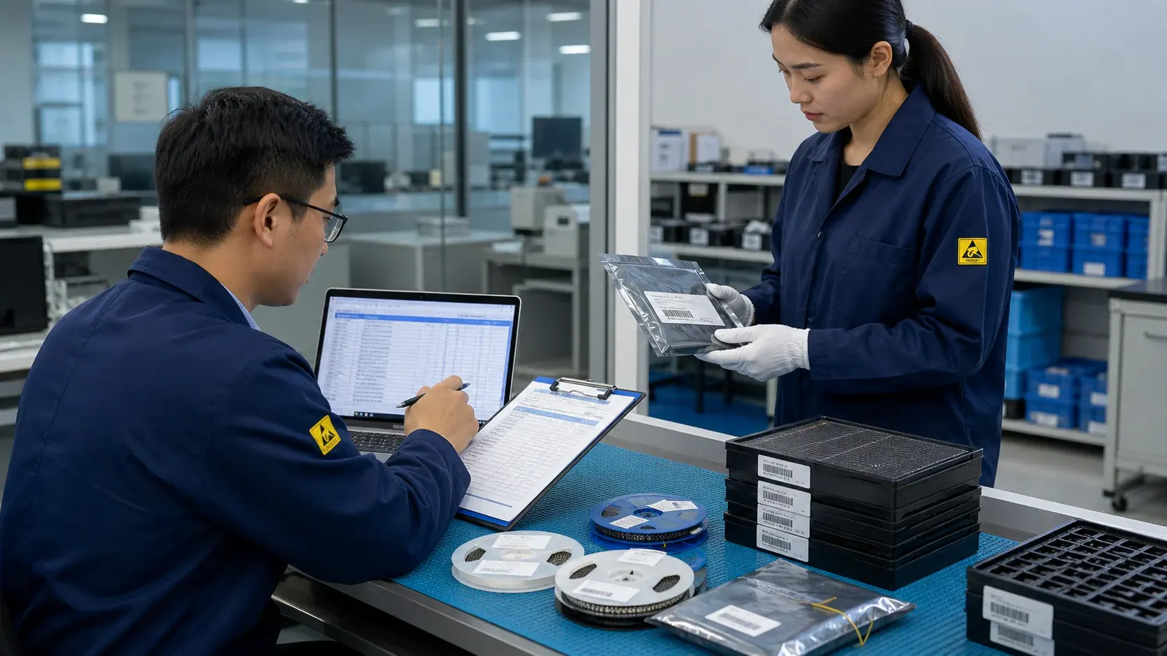
WMSIC turns product data, package visuals, BOM context, and sourcing signals into practical RFQ notes for buyers.
Model text, package form, tray or reel details, and visual evidence are reviewed together before RFQ feedback.
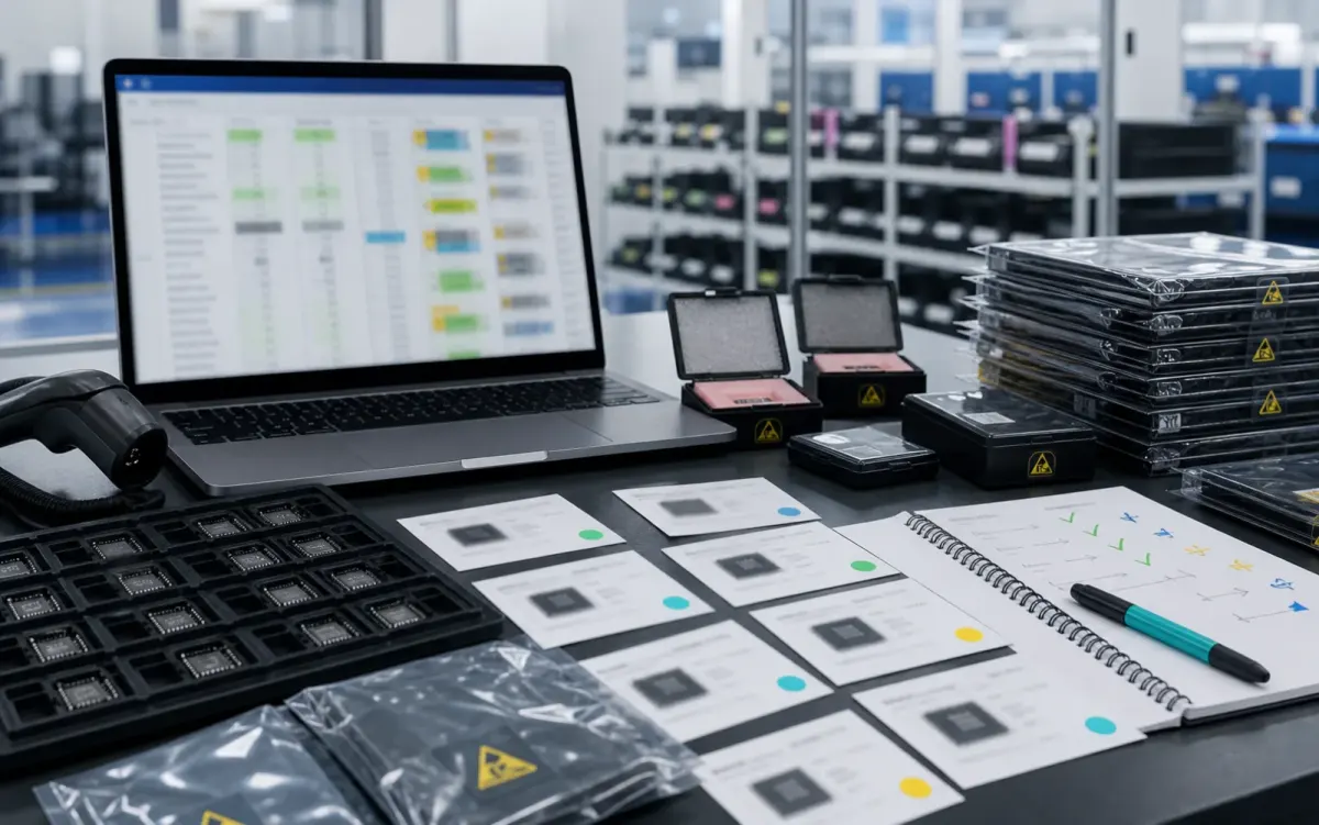
BOM lines are compared by package, parameters, quantity, and workable alternatives for cleaner sourcing decisions.
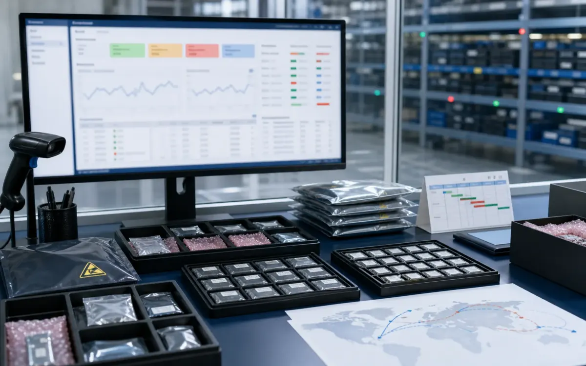
Stock routes, quotation confidence, lead-time notes, and shipment feasibility are checked before sales follow-up.
Buyer sourcing scenarios
Typical RFQ scenarios based on the WMSIC form fields, catalog data, manual review steps, and shipment preparation workflow.
The buyer shares the full part number, package requirement, quantity, destination, and available product photos so the quotation can record the exact version under review.
A multi-line BOM is organized into direct sourcing lines, lines that need package clarification, and lines where alternative-part review is permitted.
The original manufacturer part number, datasheet revision, application, critical limits, and acceptable changes are collected before possible candidates are discussed.
Sample quantity, minimum packing, package format, target date, and courier destination are kept together in one RFQ conversation.
Package photos, model markings, board context, and the quantity needed for repair help focus the sourcing review on the relevant version.
When a suffix or package note is incomplete, the response records the open difference and requests buyer confirmation before procurement proceeds.
Packing format, carton notes, invoice details, courier option, destination, and tracking handoff are coordinated around the confirmed order.
The request connects the previously used model, current demand, package evidence, target timing, and replenishment sourcing route.
Related products